| |
Electronic Control Unit
Operation Manual For Air Bio Universal Electronic Control Unit For Solid Fuel Boiler
|
|
| |
|
|
| |
|
|
| |
|
|
| |
 |
|
| |
|
|
| |
|
|
| |
Operation Manual For Air Auto TG Electronic Control Unit For Solid Fuel Boiler |
|
| |
|
|
| |
 |
|
| |
|
|
| |
Performance Data |
|
| |
|
|
| |
| Parameter Description |
AIR AUTO TG |
| Power supply voltage, V/Hz |
230/50 |
| Max power input, Watt |
1,5 |
| Environment temperature operation range, °C |
10-50 |
| Heat carrier fan max power, Watt |
450 |
| Fan max power, Watt |
350 |
| Temperature measuring range, °C |
0-200 |
| Temperature measuring accuracy, °C |
2 |
| Temperature setup range, °C |
60 - 180 |
| Temperature sensor stability, °C |
from -55 to +400 |
| Mass, kg |
1,5 |
| Fusing element, A |
3 |
|
|
| |
|
|
| |
|
|
| |
Delivery Set |
|
| |
The delivery set of AIR AUTO + includes: |
|
| |
| 1 |
Network cable with plug tip 2 m long |
1 ea. |
| 2 |
Wire for hooking-up fan with connector 0,5m long |
1 ea. |
| 3 |
Wire for hooking-up a pump, 2 m long |
1 ea. |
| 4 |
Temperature sensor with connecting wire 4 m long |
1 ea. |
| 5 |
Safety appliance |
2 ea. |
| 6 |
Operation Manual |
1 ea. |
|
|
| |
|
|
| |
|
|
| |
Safety Precautions |
|
|
1. Installation and operation of AIR AUTO TG Controller shall be performed in accordance with fire safety rules and electrical safety requirements. |
|
|
2. Installation and adjustment of the Controller shall be carried out in the presence of the qualified specialist. |
|
|
3. It is recommended to install the Controller on the boiler in such a way to prevent it from being dirtied and mechanically damaged during boiler operation. |
|
|
4. It is prohibited to use the Controller beyond the operating temperature range specified in this Operation Manual. |
|
|
5. It is prohibited to make any changes in the Controller construction at its own discretion. |
|
|
6. It is prohibited to locate the temperature sensor in fluids. |
|
|
7. During operation it is necessary to ensure that there are no any contacts of wire insulation with boiler heating up elements. |
|
|
8. Safety appliance shall be replaced only when the Controller is off (disconnected from power supply network) and with the safety appliance having the nominal specified in this Operation Manual. |
|
| |
|
|
| |
|
|
| |
Operation Manual For Air Auto HW Electronic Control Unit For Solid Fuel Boiler |
|
| |
| Parameter Description |
AIR AUTO HW |
AIR AUTO HW U |
| Power supply voltage, V/Hz |
230/50 |
230/50 |
| Max power input, Watt |
1,9 |
1.9 |
| Environment temperature operation range, °C |
10-50 |
10-50 |
| Circulating pump max power, Watt |
450 |
450 |
| Fan max power, Watt |
350 |
1000 |
| Temperature measuring range, °C |
0-95 |
0-95 |
| Temperature measuring accuracy, °C |
2 |
2 |
| Temperature setup range, °C |
40-90 |
40-90 |
| Temperature sensor stability, °C |
from -55 to +125 |
from -55 to +125 |
| Mass, kg |
1,3 |
1.6 |
| Fusing element, A |
6 |
10 |
|
|
| |
|
|
| |
|
|
| |
Delivery Set |
|
| |
The delivery set of AIR HW includes: |
|
| |
| 1 |
Network cable with plug tip 2 m long |
1 ea. |
| 2 |
Wire for hooking-up fan with connector 0,5m long |
1 ea. |
| 3 |
Wire for hooking-up the central heating pump, 2 m long |
2 ea. |
| 4 |
Temperature sensor with connecting wire 2 m long |
2 ea. |
| 5 |
Safety appliance |
2 ea. |
| 6 |
Operation Manual |
1 ea. |
| 7 |
Clip for fixing the sensor, metallic |
2 ea. |
|
|
| |
|
|
| |
|
|
| |
Safety Precautions |
|
|
1. Installation and operation of AIR AUTO HW Controller shall be performed in accordance with fire safety rules and electrical safety requirements. |
|
|
2. Installation and adjustment of the Controller shall be carried out in the presence of the qualified specialist. |
|
|
3. It is recommended to install the Controller on the boiler in such a way to prevent it from being dirtied and mechanically damaged during boiler operation. |
|
|
4. It is prohibited to use the Controller beyond the operating temperature range specified in this Operation Manual. |
|
|
5. It is prohibited to make any changes in the Controller construction at its own discretion. |
|
|
6. It is prohibited to locate the temperature sensor in fluids. |
|
|
7. During operation it is necessary to ensure that there are no any contacts of wire insulation with boiler heating up elements. |
|
|
8. Safety appliance shall be replaced only when the Controller is off (disconnected from power supply network) and with the safety appliance having the nominal specified in this Operation Manual. |
|
| |
|
|
| |
|
|
| |
Microprocessor Temperature Controller Air Auto |
|
| |
Technical Data |
|
| |
| Parameter Name |
AIR AUTO + |
AIR AUTO U |
| The voltage, V/Hz |
230/50 |
230/50 |
| Maximum consuming power, W |
1.5 |
1.5 |
| Operating range ambient temperature, °C |
0-50 |
0-50 |
| The maximum pump power, W |
450 |
450 |
| The maximum fan power, W |
350 |
1000 |
| The range of temperature measurement, °C |
0-99 |
0-99 |
| The accuracy of the temperature measurement, °C |
2 |
2 |
| The setting range of temperatures, °C |
40-95 |
40-95 |
| Endurance temperature sensor, °C |
from -55 to +125 |
from -55 to +125 |
| Weight, kg |
1,2 |
1,5 |
| A safety insert, A |
3 |
10 |
|
|
| |
|
|
| |
|
|
| |
Completeness |
|
| |
| 1 |
Network cable with the plug end, 2 m long |
1 ea. |
| 2 |
Wire connection fan output, 0.5 m long |
1 ea. |
| 3 |
Wire pump, 2 m long |
1 ea. |
| 4 |
Temperature sensor with wire, 2 m long |
1 ea. |
| 5 |
Fuse |
1 ea. |
| 6 |
Operating instructions |
1 ea. |
|
|
| |
|
|
| |
|
|
| |
Precautions |
|
|
1. Device installation and operation must be conducted in accordance with the requirements of fire safety and electrical safety rules. |
|
|
2. Device installation and configuration must be implemented by a qualified specialist. |
|
|
3. Device installations must ensure the absence of impurities, mechanical and thermal damage during its operation. |
|
|
4. Do not use the device outside temperature range specified in this instruction. |
|
|
5. Do not make changes in the construction of the device. |
|
|
6. Do not place the temperature sensor directly in the liquid. |
|
|
7. During operation it is necessary to provide the absence of the contact of wire the insulation and the heating parts of the boiler. |
|
|
8. The replacing of the fuse must only be performed when the network power device is disconnected by the fuse rating specified in this manual. |
|
| |
|
|
| |
|
|
| |
Operation Manual For Air Bio Pid Microprocessor-Based Temperature Controller |
|
| |
|
|
| |
 |
|
| |
|
|
| |
Introduction |
|
| |
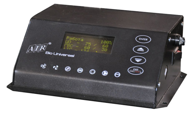
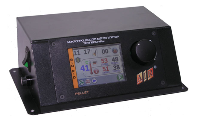
AIR BIO PID Temperature Controller is designed for control of the Central Heating Boiler equipped with the burner and worm feeder. The Controller controls gradual change of the fan power by switching on the Central Heating pump and hot water supply. AIR BIO PID can be used in pellet burners with automatic firing.
Owing to the capability of connecting expansion modules to AIR BIO PID Controller via RS 485 interface, the Controller is able to operate the mixer valve of three-or-four-way valve and the additional mixing pump, frequency converter (for powerful pumps) as well as it is able to control the level of fuel in the bunker. In addition, GSM module can be connected to the Controller, and this module is used for control of the boiler operation through mobile network.
AIR BIO PID Controller can also work along with the room thermostat working based on the principle: on/off.
AIR BIO PID controls two independent processes:
a) temperature regulation:
PID algorithm sets the required boiler capacity to obtain the needed temperature, what results in no violent changes of temperature in the chimney hole as well as in the combustion chamber. The burning process can be permanent without breaks with capacity from 1% (keeping fire state) up to 100% (maximum boiler capacity).
b) combustion process regulation:
Automatic fuel dosing. The unique software automatically changes fuel amount. AIR BIO PID Controller is manufactured and released in the metal housing as a standalone unit for installation on the boiler or in any other place convenient for you.
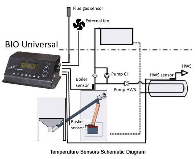
The standard list of equipment includes:
- central heating temperature sensor
- hot water supply temperature sensor
- basket temperature sensor;
- smoky vapors temperature sensor;
- burner connecting cord;
- power-supply cord
Benefits and advantages of using AIR BIO PID Controller:
- ecology: low level of dust and gases harmful for the environment, low temperature of flue gases
- cost-effectiveness: efficient fuel consumption |
|
| |
|
|
| |
|
|
| |
Operation Manual For MPT Air Logic + Temperature Controller |
|
| |
|
|
| |
 |
|
| |
General Data |
|
| |
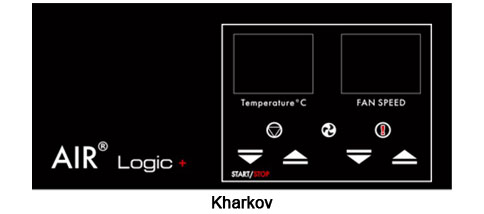
Microprocessor-based temperature controller (henceforth MPT AIR Logic +) is designed to ensure cost-effective and safe operation of a solid fuel boiler with manual load of fuel by controlling operation of pressurizer fan (or exhaust fan) and circulating pump (henceforth CP) of the heating system. MPT AIR Logic + is the sophisticated smart device that functions in completely automatic mode.
To enhance efficiency and safety of the fuel burning process the effective proportional-integral-differential (henceforth PID) algorithm of fan power control has been implemented in "Automatic Operation" mode, and this allows increasing duration of fuel burning up to 15-20% in comparison with the classic on-off (hysteresis) control. In addition, use of PID algorithm improves the accuracy of maintaining heat carrier temperature on exit from the boiler set up by the user, improves environmental performance of fuel burning process, and enhances safety and comfort in operating solid fuel boilers.
"Anti-Freezing" and "Error" modes are intended to ensure safe operation of the boiler and the heating system as a whole.
There is the Setup Menu in the device in case of necessity to correct factory settings, and in order to enter the menu one should turn on the device holding button 1, and in order to save the corrected data and move to the main menu one should press and hold button 4 within 5 seconds. |
|
| |
|
|
| |
|
|
| |
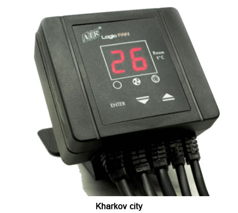
Operation Manual For "logic Fan" Electronic Control Unit For Fan Heater |
|
| |
|
|
| |
 |
|
| |
|
|
| |
Introduction |
|
| |
Product Purpose and Delivery Set |
|
| |
AIR LOGIC FAN Control Unit (hereinafter referred to as Controller) is designed to control fan heaters and a heating pump (valve).
The control unit applies PID algorithm during its operation what allows maintaining the preset temperature in the premises with high accuracy and save power by automatic decreasing fan heater rpm once the preset temperature is achieved.
AIR LOGIC FAN is the sophisticated unit and it functions in completely automatic mode.
AIR LOGIC FAN delivery set includes:
|
|
| |
| 1 |
Network cable with plug tip 2 m long |
1 ea. |
| 2 |
Wire for hooking-up fan, 4 m long |
1 ea. |
| 3 |
Wire for hooking-up central heating pump (valve), 4 m long |
1 ea. |
| 4 |
Central heating temperature sensor with connecting wire 4 m long |
1 ea. |
| 5 |
Room temperature sensor with connecting wire 0,5 m long |
1 ea. |
| 6 |
Safety appliance |
1 ea. |
| 7 |
Operation Manual |
2 ea. |
| 8 |
Clamp for fastening |
1 ea. |
|
|
| |
|
|
| |
Installation Requirements |
|
| |
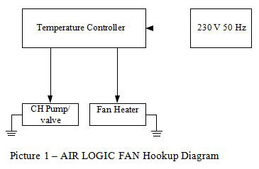
Works on AIR LOGIC FAN installation and adjustment shall be carried out in the presence of the qualified specialist. All installation works associated with installation/removal of the unit or electric wiring shall be carried out only after power cut. Hookup diagram for the fan and central heating pump is shown on Picture 1. |
|
| |
|
|
| |
 |
|
| |
|
|
| |
Attention! Improper connection of wires might result in damage of the unit!
AIR LOGIC FAN Application Benefits
If using AIR LOGIC FAN Control Unit for fan heaters the operator gets the following advantages:
- achievement of the required temperature in the premises by regulating fan rpm with the help of PID algorithm
- shutdown of HTF supply to the fan heater (when using a valve or a pump) once the heat carrier temperature goes down
- prevention of room overheat. |
|
| |
|
|
| |
|
|